Request a
calculation form

Home / Systems / Composite slab system

Composite slab system

Fast and light slabs solutions for your project. Our range of composite metal floor decking profiles is designed to support the weight of the concrete and execution loads during the construction phase, in addition to collaborating at a strength level with the concrete once it has set.
  • Versatile systems that adapt to any type of structure
  • Reduce execution time
  • They achieve fire resistance of up to REI 240 without the need to project
  • They allow spans of up to 5 m without the need for shoring
  • Arrange the floor embedded in the structure to increase the free height
sketch of embedded collaborative forged system - scheme

Composite floor deck

It is a unidirectional mixed slab in which the concrete is poured over a corrugated sheet profile that serves as formwork and, in turn, positive reinforcement. When the concrete sets, this profile collaborates with the concrete, absorbing tensile stresses.

1. Principal structure
2. Composite flooring profile
3. Anti-cracking armor
4. Concrete

Related information

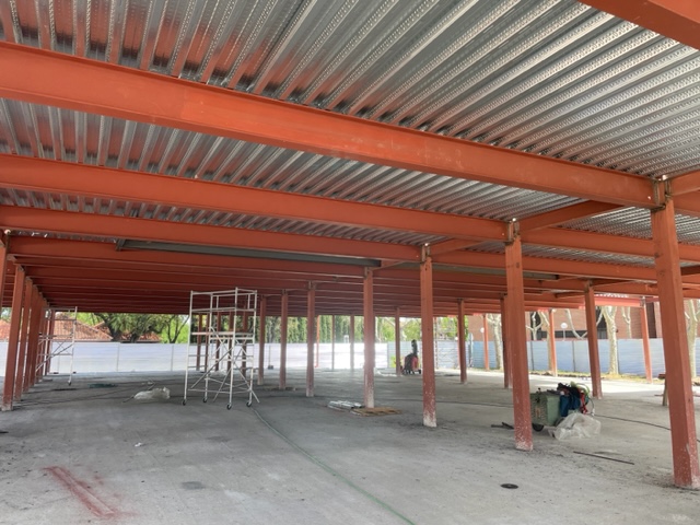
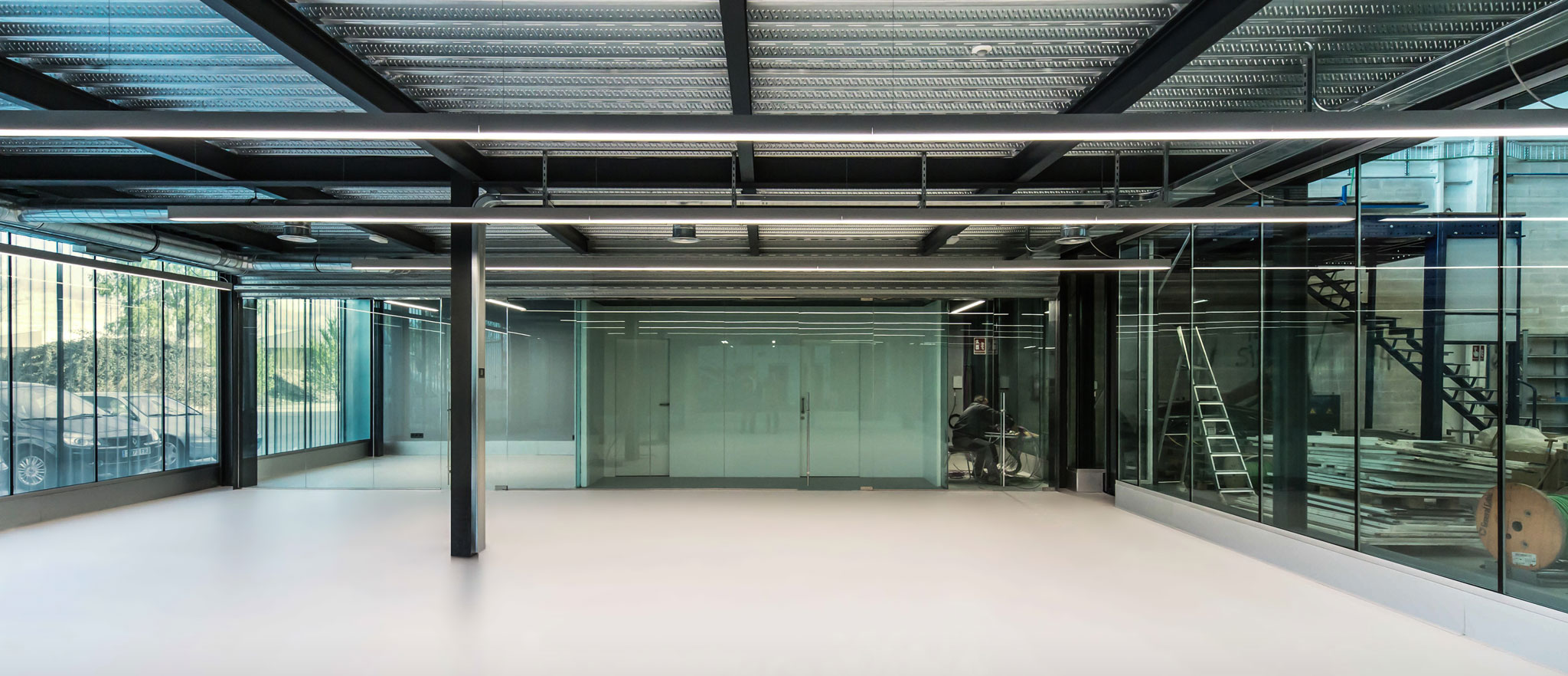
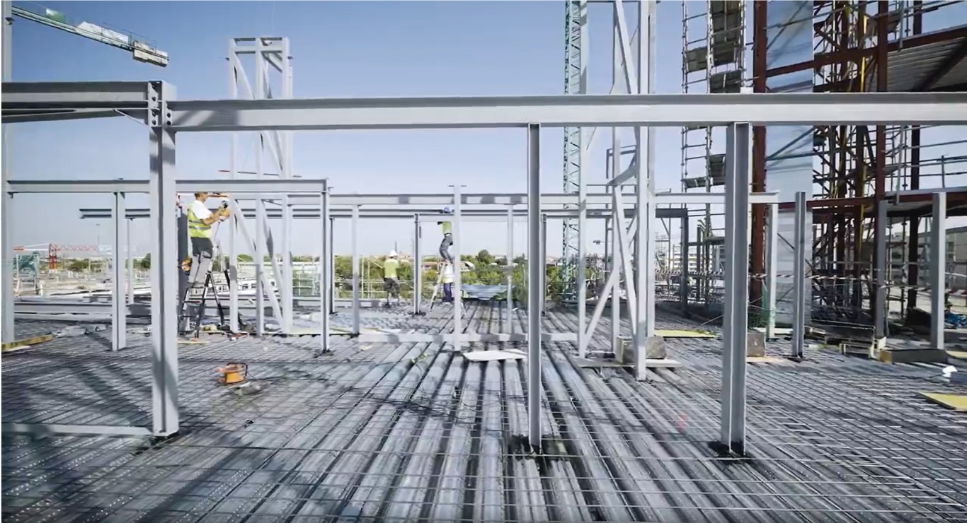
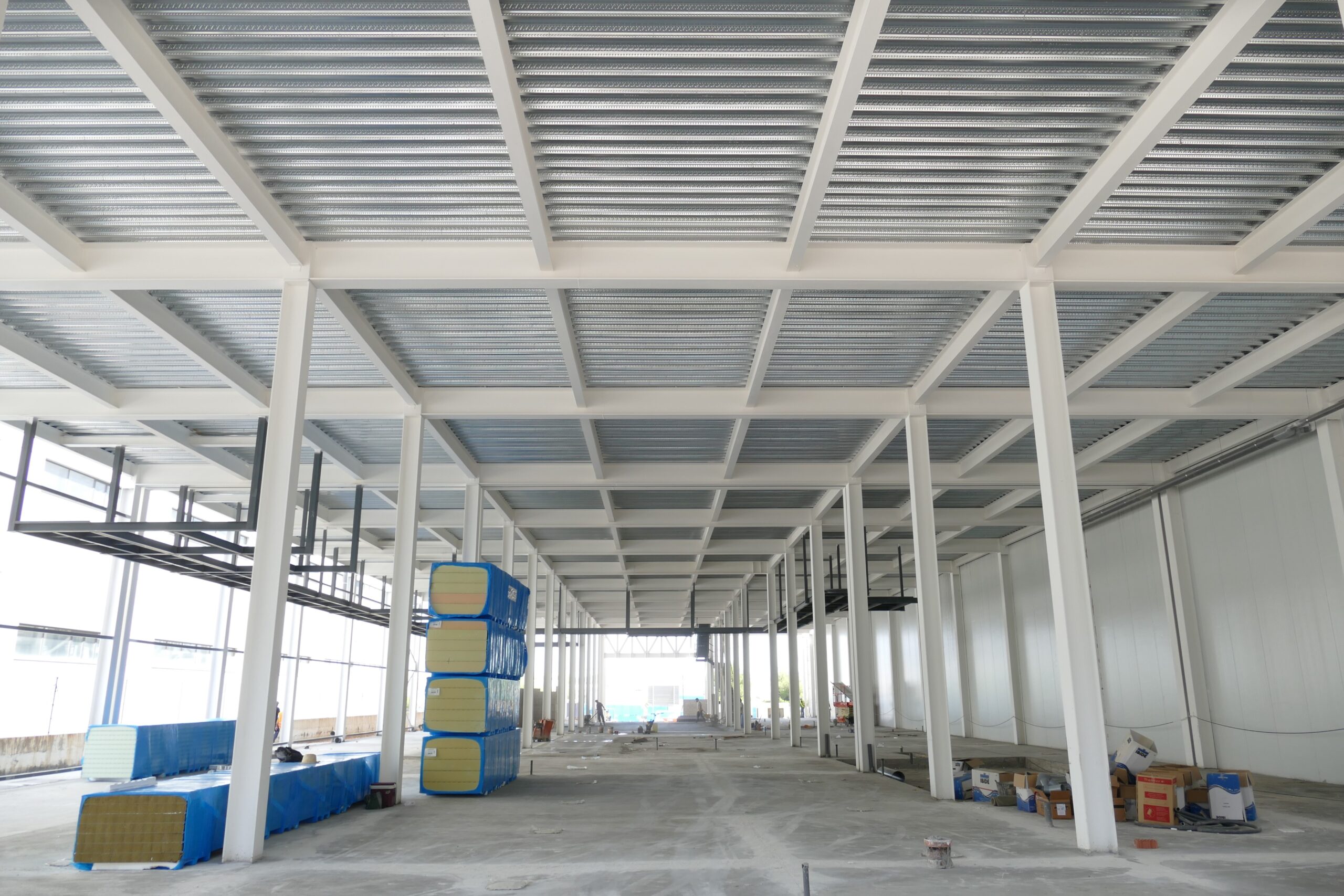
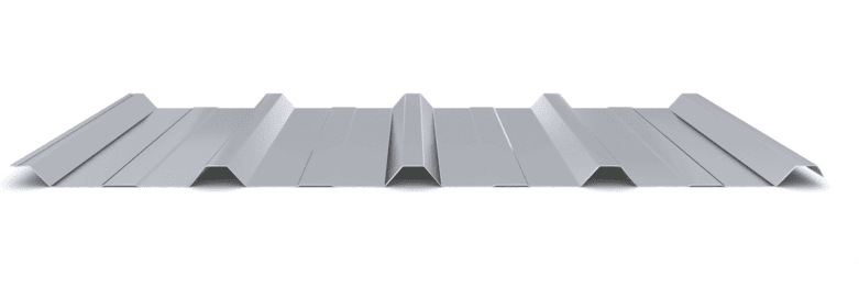
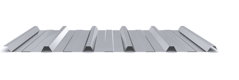
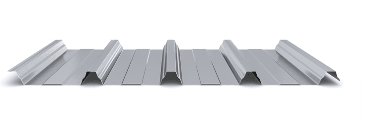
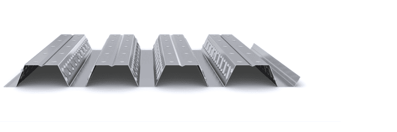
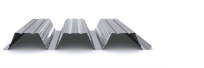
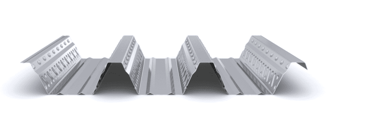
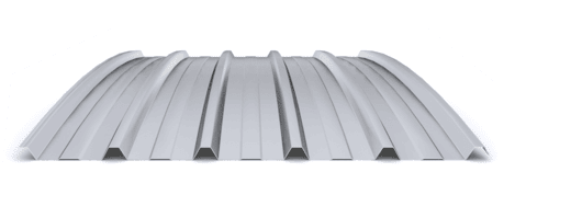
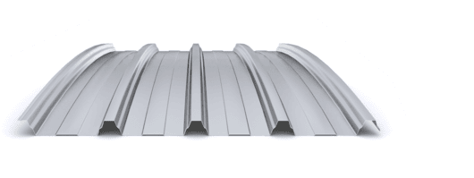
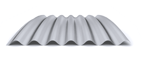
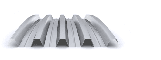
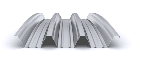
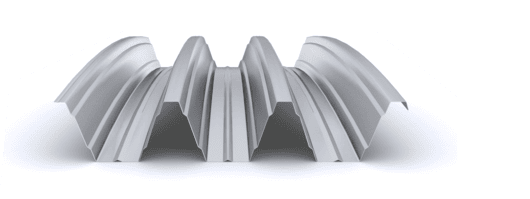
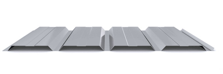
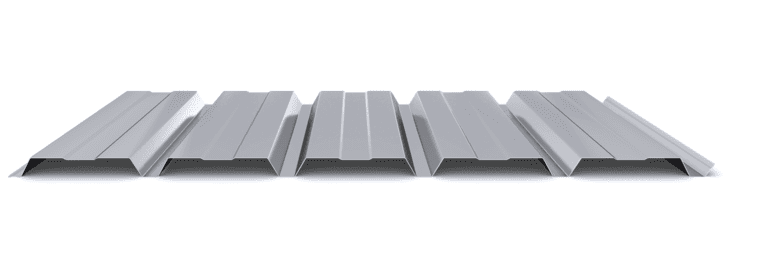
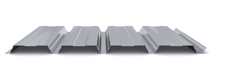
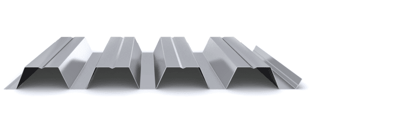
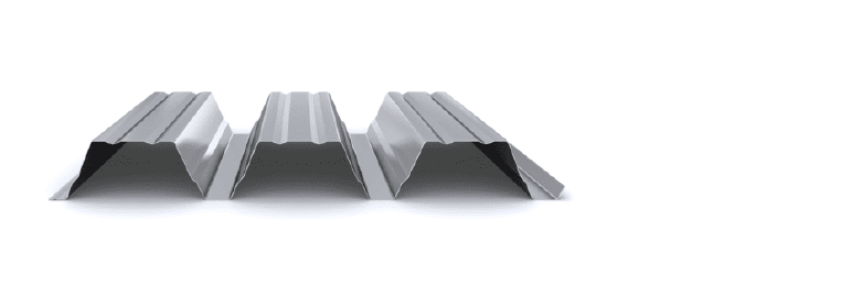
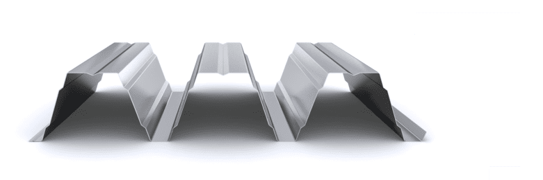
The composite slab system is made up of a galvanized metal composite floor deck that serves as formwork for a concrete slab executed in situ. Once the concrete has reached the characteristic strength of the project, the ribbed profile and the concrete slab work together.

During the formwork phase, the profile supports the loads of execution and pouring of the concrete. In the mixed phase, the profile collaborates with the concrete through specific embossing, acting as positive reinforcement and forming a mixed cross section. It is for this reason that the composite floor deck is also known as a composite or mixed slab.

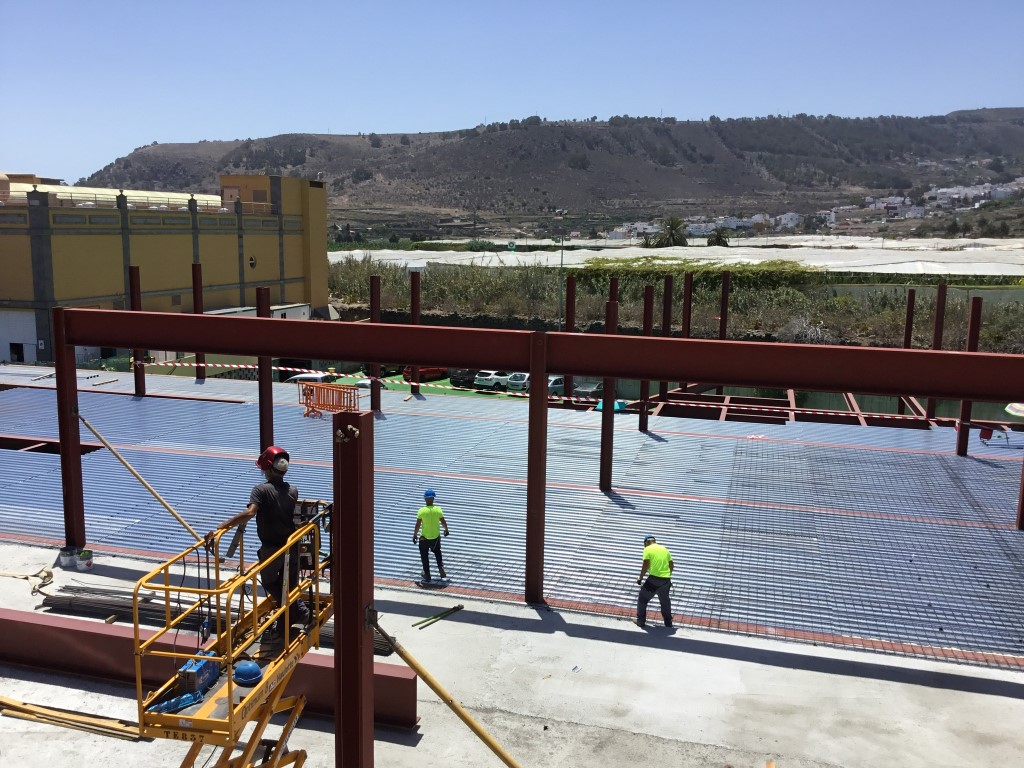
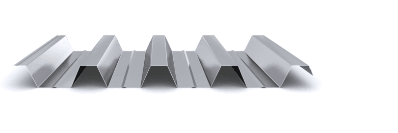
Using this solution, light slabs can be made, with a self-weight of less than 2 kN/m², through an agile and simple execution procedure, especially in those slabs that do not require shoring. In those cases in which shoring is not an impediment, greater separations between the support beams of the slab can be achieved.

  1. The structure, formed by support beams every 3-5 m, is responsible for supporting the main actions of the floor, guaranteeing its integrity and stability.
  2. The composite metal floor decking profile constitutes the first layer of the slab and is placed and fixed on the structure. This element supports the execution loads during the formwork phase and, in collaboration with the concrete, the design loads in the mixed phase, meeting the corresponding mechanical requirements.
  3. The reinforcements in the composite floor decking are organized according to their function: the anti-cracking reinforcement or mesh, necessary in every slab to control cracks on the upper face of the slab, the negative reinforcement, generally included in the amount of the mesh to reinforce the negative moment zones on the supports, and positive/fire reinforcement, necessary only when there are fire requirements greater than REI30, providing additional reinforcement in fire resistance.
  4. The concrete, which is poured directly onto the composite floor deck profile, together with it forms the mixed section of the slab and provides the necessary strength and rigidity to withstand the design loads.
  5. Composite floor deck system sketch - scheme

Composite floor deck system sketch – scheme

SYSTEM COMPONENTS SYSTEM ACCESSORIES
1. Composite Slab | INCO 70.4 Composite Floor Deck a.-Trimming | Cantilever Edge Trim
2.-Reinforcement | Anti-cracking and Negativesb.-Trimming |Edge Trim
3.-Structure | Concretec.-Trimming | Fastening Strap
d.- Tightness | Bottom Joint
  • Industrial: Warehouses and production centers
  • Logistics Center: Warehouses and distribution centers
  • Commercial: Canopies, offices and commercial surfaces
  • Infrastructure: Stations and airports
  • Public: Schools, markets and hospitals
  • Sports: Stands, sports courts and pavilions
  • Agricultural: Stables, farms and sheds
  • Packaging and transportation: The composite floor decking profiles are grouped in strapped packages of 20-25 sheets, with a maximum length depending on the type of profile and a maximum weight of 1,500 kg. Each package includes an identification label with details of the manufactured product, order and destination. Transportation is preferably carried out in a truck closed with a tarp to prevent the material from being exposed to the elements.
  • Reception and unloading: Before unloading, it is verified that the material matches the geometry and thickness specified in the project. Unloading is carried out with the appropriate lifting means, and preferably directly in the installation area, to minimize movements on site.
  • Storage and protection: On site, the packages are stored in a covered and ventilated area on inclined wooden sleepers and are protected from humidity with breathable tarps. Packages are not stacked more than three high and no other materials are placed on them.
  • Installation on the structure: The packages are placed on the main beams, close to the supports, ensuring that the structure can support their weight. They are oriented in the direction of installation and are placed manually, sheet by sheet, under the supervision of the Construction Management. In the case of large pieces, the sheets are lifted individually from the ground to their position on the slab.

Featured Products

  • Maximizes clearance between floors
  • Unpropped up to 4 m
  • Thickness: 0,75 – 1,2 mm
  • Slab depth from 110 mm
  • Up to 2.000 m² / transport
  • Light and strong
  • Unpropped up to 5 m
  • Thickness: 0,75 – 1,2 mm
  • Slab depth from 140 mm
  • Up to 1.600 m² / transport
  • Robustness and acoustic comfort
  • Fire resistance and composite beams
  • Thicknesses: 0,75 mm – 1,2 mm
  • Total slab thickness from 140 mm
  • Up to 1.600 m² / transport

Projects

Start designing yout project

Request calculation report

Complete the form below to receive a detailed report justifying the most suitable enclosure profile. You will receive the information as soon as possible.

Building characteristics
Industrial roof application loads
(1) For sections of the roof profile with 2, 3, 4 or more supports, indicate the greatest distances between supports that appear in your project.
Type of environment
Attached documentation
Additional comments
Contact information
Project data
Building characteristics
Application loads for the industrial facade
(1) For sections of the façade profile with 2, 3, 4 or more supports, indicate the greatest distances between supports that are presented in your project.
Type of environment
Attached documentation
Additional comments
Contact information
Project data
Building characteristics
Deck loads
(1) For sections of the roof profile with 2, 3, 4 or more supports, indicate the greatest distances between supports that appear in your project.
Type of environment
Attached documentation
Additional comments
Contact information
Project data
Structure features
Composite slab characteristics
(1) For the sections of the composite slab with 2, 3, 4 or more supports, indicate the greatest distances between supports that appear in your project. Span length < 5,00 m.
Type of environment
Attached documentation
Additional comments
Contact information
Project data
Building characteristics
Characteristics of the facade
Roof typology

(1) Indicate the length of the span of the arch, which is the greatest horizontal distance between the supports of the curved roofing.

(2) Plan-view dimension representing the full length of the curved roof measured perpendicular to the arch span.

(3) Specify the obstructed area under the canopy, in square meters, as a proportion of the total area of the front or side (transverse or longitudinal) façade, in order to calculate the obstruction factor. If it is a closed construction or there is no obstruction area, indicate 0 m².

Environment characteristics
Type of environment
Attached documentation
Additional comments
Contact information
Project data

Latest projects